
Introduction
If you’re looking for a simple way to achieve a remote on/off for something that plugs into a wall, you can possibly find products such as this for cheaper, and can control more. However, for internal hardware and things such as a power supply (I installed this into my original xbox for remote on/off), this is the way to go.
Requirements
- Logisys Remote Control Molex Connector Kit
- A relay, differs depending on what the project is used for.
- 9 volt supply line or battery
- Soldering Iron
- External Enclosure (If Needed)
Procedure
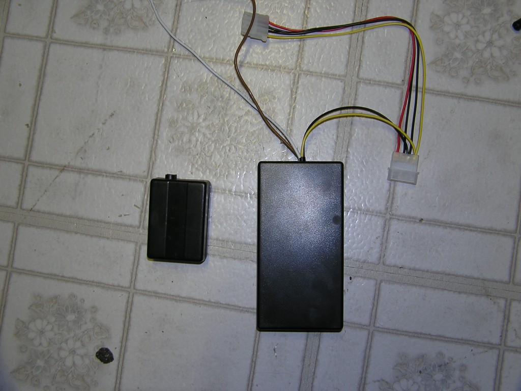
Originally, I started this project to control cold cathode lights that I have set up in my room. After buying theLogisys Remote Control Molex Connector Kit however, I realized what a mistake I had made. In order for the Remote Control Connector to work, the power supply needed to be continuously running, but due to the fact it could overheat and most of the time it would be running for no reason, I decided I need to take this thing apart and tinker around.
When it arrived, it looked exactly as seen below. As you can see, the 12v in not only powers the device’s RF receiver, but also is for the 12v out. The controllers are run by a 12V Alkaline battery (type VR22/CN22/CN23A) and are just 2 buttons for on/off, and a red LED that flashes when a button is pressed.
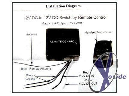

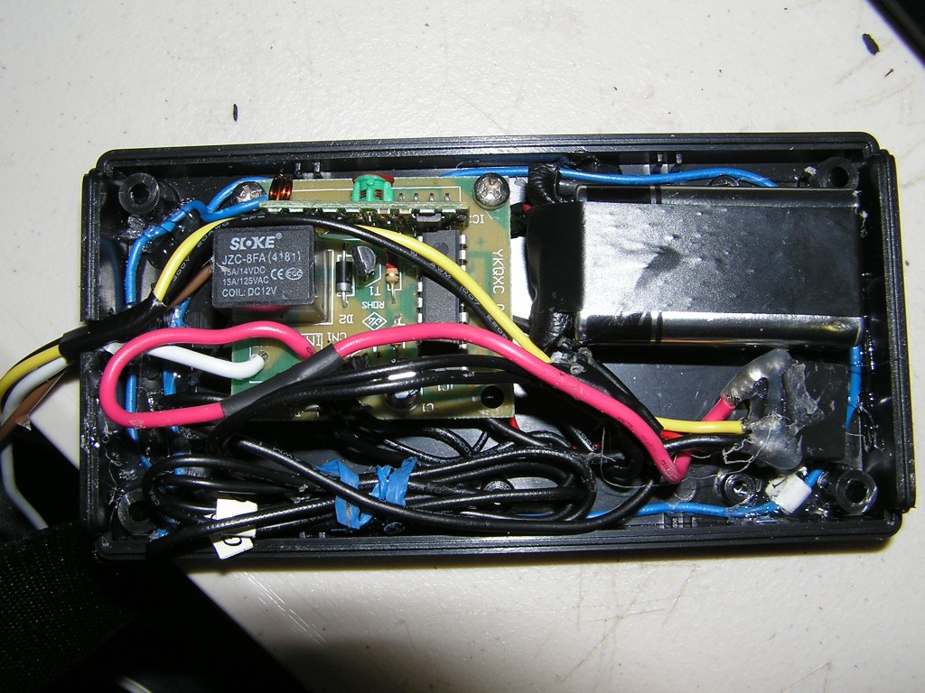
I took apart and gutted the case, and after testing, I found the solder point where the 12v In is connected to the 12v Out wire. My first priority was to modify it so that instead of 12v Out, I could choose what voltage I want to be connected when I press on, by adding another wire. In theory, it should look like:

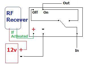
Unfortunately, the 12v In is not only connected to the same point that is used to power the RF receiver, but also to the 12v Out wire. I tried to desolder the path, but it seems like the solder was just in case an internal trace was damaged, so I ended up having to dremel in between the two to separate it. I then soldered another wire to the lone point, which simply made it so that when the device has anywhere from the 9-12v it needs to power the RF, it also can trigger the relay which connects the In and Out, as seen in the schematic above.

Now, the way a power supply works is that when a certain wire (normally the green one on the 20-24 pin connector) is grounded, the power supply turns on. Therefore, if I ground the In point, then when the ON button is pressed, it connects the Out wire to ground. Essentially, when I connect the In to ground, then when I press ON it grounds Out (which is connected to the green wire on the power supply) and turns on the power supply. The one problem with this is the fact that the 9-12v needed from the power supply isn’t there since the power supply is off. The next thing I did was connect the whole thing to a 9v battery, and this worked perfectly.
Problem solved? Not quite. The problem with the 9v battery is that in the ON position, it quickly drained, causing the relay to go back to OFF. Basically, I needed to make it so when the 9v is turned on, it turns on the power supply, and the power supply cuts the 9v off and powers the relay. This means that when the power supply is turned on, the battery is disconnected and the power supply keeps itself on from the 12v it produces. How did I solve this? With another relay! This is what it looks like:

Now, the above image can get confusing. To make it a bit simpler, I’ve put numbers to explain.
1- This point is the 9v in for the RF receiver and the ON/OFF relay. It’s wired like this because once the power supply is turned on, it switches from the 9v to 12v
2- This point is the 12v in for the RF receiver and the ON/OFF relay, explained above.
3- This is the point where the 9v switches to 12v when the device is turned on. This enables the battery not to be drained when the power supply is on.
4- This is the 12v for the battery saver relay, which is only turned on once the purple is grounded.
5- These are the two grounds for the relays. It is wired up to both the 9v and power supply ground.
6- This is the power supply ground, which is connected to the 9v ground.
7- The multiple 7’s show the path that the ground from the power supply travels to the purple. It is connected in the ON/OFF relay when the on button is pressed, powering up the power supply and enabling the 12v to power the second (battery saver) relay. When the off button is pressed, the purple dot’s connection to ground is disconnected, and the power supply powers off.
And now you’re done! I put my relays in an enclosure to keep it from shorting on other objects. It should be noted that to keep a slim profile, a small 12v battery SHOULD be able to work in place of a 9v, though i haven’t tested it.

Conclusion
Above are the I took pictures of my new enclosure next to the original one. Its slightly bigger in the front, and almost identical on the side, however it now fits another relay and a 9v battery internally. I also hooked up a molex connecter splitter so it can be supplied the 12v through usb.
Leave a Reply