Introduction
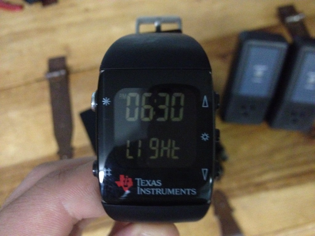
I’ve been kicking around the idea to remotely control my room’s lights for a while, but I never got around to actually designing it. I picked a Logisys Remote Control Wall Outlet set, and it worked fine for controlling my single light that connected to an outlet, but I wanted to think big and expand it to the ceiling lights, which were connected to a wall switch. When the Chronos watch was released, I immediately began to play with the code running it, and realize that this could be used to control real world objects. The ability toggle my lights with my watch helped push this project into its planning stages.
Requirements
- Logisys Remote Control Wall Outlet
- eZ430-Chronos Wireless Watch Development Tool
- Python
- PySerial (Serial Communication for Python)
- Chronos Outlet Control Bundle: This is both the Arduino Code, and the Python script I created.
- An Arduino
- Soldering Iron
Procedure
The Chronos watch has some amazing features, which you can see by clicking the product page for it above. One of the coolest features (and the reason this watch is different from anything else) is the ability to reprogram the watch, and use all it’s sensors for any use you want. On the stock watch software, there is application that lets you control powerpoints by using two buttons, so I dived into the code to find that specific function, and it was easier than I thought, since no reprogramming was necessary. What happens is, when you press a button, the watch relays that information via RF to the USB receiver. Therefore, the software was the one who was detecting the button being pressed, and deciding what to do next. If I could cut in between the software and read those button presses, I could make them do anything.
I used python to achieve this, and the code is below:
import serial, array, csv, time

def startAccessPoint():
    return array.array('B', [0xFF, 0x07, 0x03]).tostring()

def accDataRequest():
    return array.array('B', [0xFF, 0x08, 0x07, 0x00, 0x00, 0x00, 0x00]).tostring()

# ser = serial.Serial(5,115200,timeout=1)
ser = serial.Serial(6)
print "Connected to RF"
arduinoser = serial.Serial(5)
print "Connected to Arduino"

#Start access point
ser.write(startAccessPoint())
print "Start RF Access Point"

while True:
    print "True Loop"
    #Send request for acceleration data
    ser.write(accDataRequest())
    print "Data Request"
    accel = ser.read(7)
    print "Read Serial"
    time.sleep(.1)

    if ord(accel[6]) == 18 and ord(accel[5]) == 7 and ord(accel[4]) == 6
and ord(accel[3]) == 255 and ord(accel[2]) == 0 and ord(accel[1]) == 0 and ord(accel[0]) == 0:
        print "-----------------First Button Toggle"
        arduinoser.write("Q")

    if ord(accel[6]) == 50 and ord(accel[5]) == 7 and ord(accel[4]) == 6
and ord(accel[3]) == 255 and ord(accel[2]) == 0 and ord(accel[1]) == 0 and ord(accel[0]) == 0:
        print "-----------------Second Button Toggle"
        arduinoser.write("A")

    time.sleep(1.3)
    print "Loop Ended"

ser.close()
arduinoser.close()
As you can see from the code, the Arduino connects via serial to both the RF receiver, and to an Arduino (which we will get into in a bit). It then requests for acceleration data (which contains which button was pressed), and if the data is found in the string received, it sends sends a Q or A depending on which button was pressed. That’s it for the python code, now onto the Arduino!
I wanted to be able to control two outlets (though it is possible to control as many as you want, I’ll get into that at the end), so I knew I had to be able to toggle four different buttons (1 ON, 1 OFF, 2 ON, 2 OFF).The first thing I had to do was gut the controller used for controlling the Logisys Remote Control Wall Outlet, and that was strait forward enough. Next, I soldered wires from the Arduino to the four relays, which will toggle the controller buttons. The relays were then wired directly to the remote, as you can see below.
Next, I added a USB hub so that the RF receiver and the Arduino can both fit nicely into a case, which you can see I borrowed from my vgInteractive project. The final thing I did was add a green and orange light (scrapped off an old PC), and also wired that to the Arduino, so that I can see the status of the lights (which one is on, which one is off) just by looking at the enclosure. Overkill? You bet. Here’s the completed enclosure:
The final part is the Arduino code, which is incredibly simple – it uses the relays to press the corresponding buttons on the remote:
int off2power = 2;
int off2ground = 3;
int on2power = 4;
int on2ground = 5;
int on1power = 6;
int on1ground = 7;
int off1power = 8;
int off1ground = 9;

int secondled = 12;
int firstled = 11;
int val; // Value read from the serial port
int firststat = 0;
int secondstat = 0;

void setup()
{
  pinMode(on1power, OUTPUT);
  pinMode(off1power, OUTPUT);
  pinMode(on1ground, OUTPUT);
  pinMode(off1ground, OUTPUT);
  pinMode(on2power, OUTPUT);
  pinMode(off2power, OUTPUT);
  pinMode(on2ground, OUTPUT);
  pinMode(off2ground, OUTPUT);
  pinMode(firstled, OUTPUT);
  pinMode(secondled, OUTPUT);
  Serial.begin(9600);
  Serial.flush();
}

void loop()
{
  // Read from serial port
  if (Serial.available())
  {
    val = Serial.read();
    Serial.println(val);

 ////////////////////////////////////////////////////////////////////// First Device
      if (val == 'Q') //ON
    {
      if (firststat == 0)
      {
        digitalWrite(on1power, HIGH);
        digitalWrite(on1ground, LOW);
        digitalWrite(firstled, HIGH);
        delay(700);                  // wait .5 a second
        digitalWrite(on1power, LOW);
        firststat = 1;
      }
      else
      {
        digitalWrite(off1power, HIGH);
        digitalWrite(off1ground, LOW);
        digitalWrite(firstled, LOW);
        delay(700);                  // wait .5 a second
        digitalWrite(off1power, LOW);
        firststat = 0;
      }
    }
////////////////////////////////////////////////////////////////////// Second Device
    if (val == 'A') //ON
    {
      if (secondstat == 0)
      {
        digitalWrite(on2power, HIGH);
        digitalWrite(on2ground, LOW);
        digitalWrite(secondled, HIGH);
        delay(700);                  // wait .5 a second
        digitalWrite(on2power, LOW);
        secondstat = 1;
      }
     else
     {
      digitalWrite(off2power, HIGH);
      digitalWrite(off2ground, LOW);
      digitalWrite(secondled, LOW);
      delay(700);                  // wait .5 a second
      digitalWrite(off2power, LOW);
      secondstat = 0;
     }
    }
  }
}
All done! Below are images and a video of the finished product:
Conclusion
There are a few things that can be done differently, but keep in mind that this script is over two years old. However, something I would change is the two device limit. As it is, the top button is device #1, and the bottom is #2. However, if I were to return to this project, the top button would cycle through device numbers, while the bottom would activate/deactivate them. That way, there could be more device possibilities then you would need.


Leave a Reply