
Introduction
This project is the slow growing progression of a project I started for the original Xbox, specifically for Halo 2. To date this, the first post on the Xbox-scene forums was done Oct 7 2006, 01:19 AM. However, as the project grew, I realized the potentials of expanding this from an Xboc project, to making this for PC gaming in general.
Requirements
- TBD (In progress)
Procedure
The “rifle” I chose to use in this second prototype is actually a Laser Tag gun. While I originally planned on using an airsoft M4 replica as the foundation, this casing allowed more flexibility due to it’s size as it has about three times the width to work with. Since the initial plans for the M4 version was had an external box containing the Arduino and recoil functionality, going with the laser tag gun removed the need.

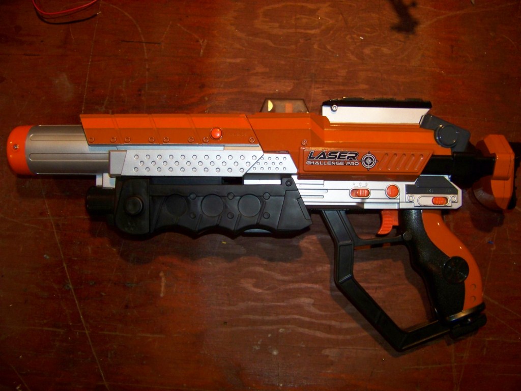


As you can see above, the rifle has an adjustable buttstock (which is later replaced), and bipods. The LCD screen is hard to see, but it contains progress bars for both remaining health and ammo. Regardless if I use it or not, the space is there to put in another display if needed. The final important feature that is perfect is the removable barrel, which is almost the same length as the rifle itself. Since the barrel is completely empty, all the big components will reside in it and will connect to the components (trigger, buttons) of the main body when attached.
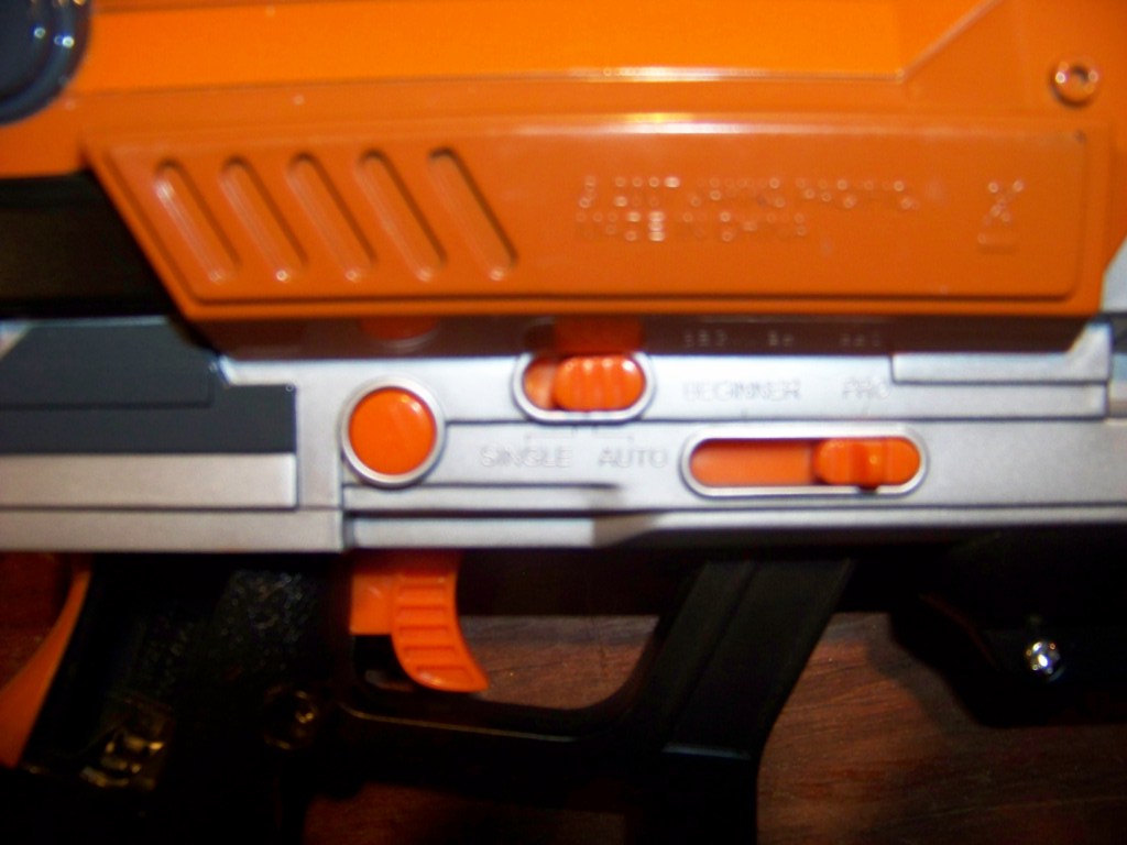
Another reason I chose this model is the abundance of buttons and switches. The trigger’s purpose is obvious, while the “A” button’s original function started the laser tag game. For now, I have no use for it. The switch in the middle is a Semi/Auto switch, so when set to the left it fires single round bursts, while to the right it will fire in a secondary manner, which for now is a three round burst. The final switch, to the very right, is labelled Beginner – Pro. It switches like a normal switch, and before disassembly, I could not find a difference in modes. Once disassembled, I found something unusual. It wasn’t connected to anything. It wasn’t even a switch, just a slider with a spring, to keep in in place. In the end, I just removed it, and its now an empty spot.

The components on the other side (shown above) have great uses. The switch to the very right is an on – off switch, and is now connected directly to a couple of portable USB chargers. The middle “R” button originally reloaded the rifle. The switch to the very left has 3 choices, A, B, or C. This is now programmed so that A mode shuts off the red laser, and pulses the IR one on the trigger press. C mode (The middle) leaves the red laser constantly on, and pulses IR. B mode pulses both red and IR lasers on trigger pull.

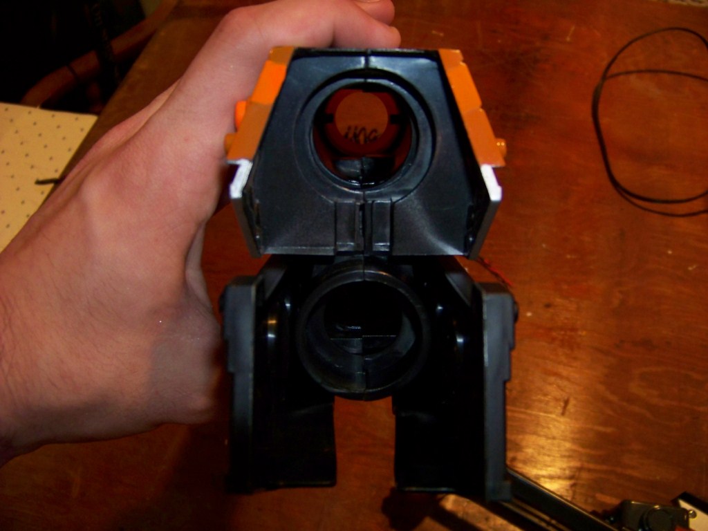

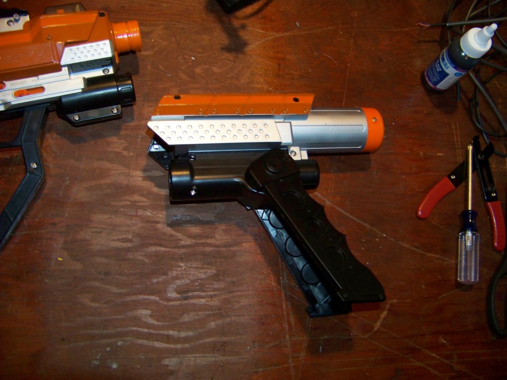
These pictures just show the front and back of the barrel detached, and the final picture shows the front of the actual gun. I removed everything blocking the front of the gun, so that I can feed wires through from the barrel.
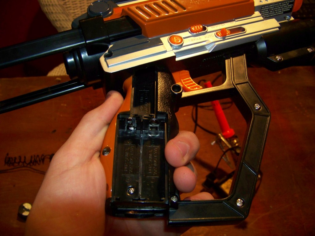


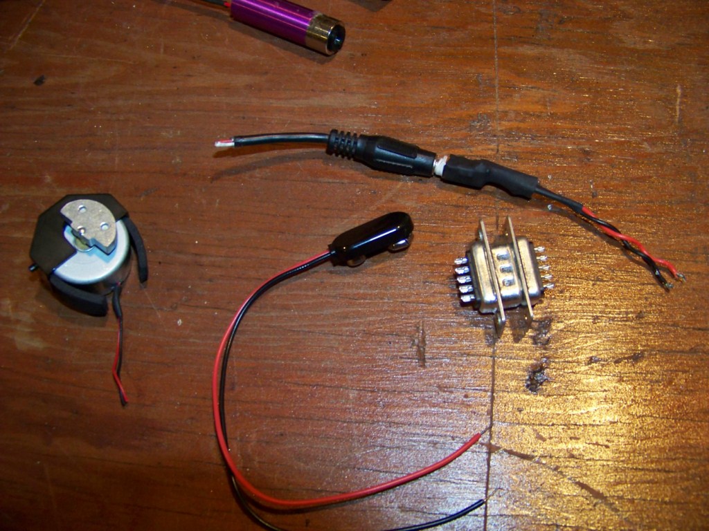
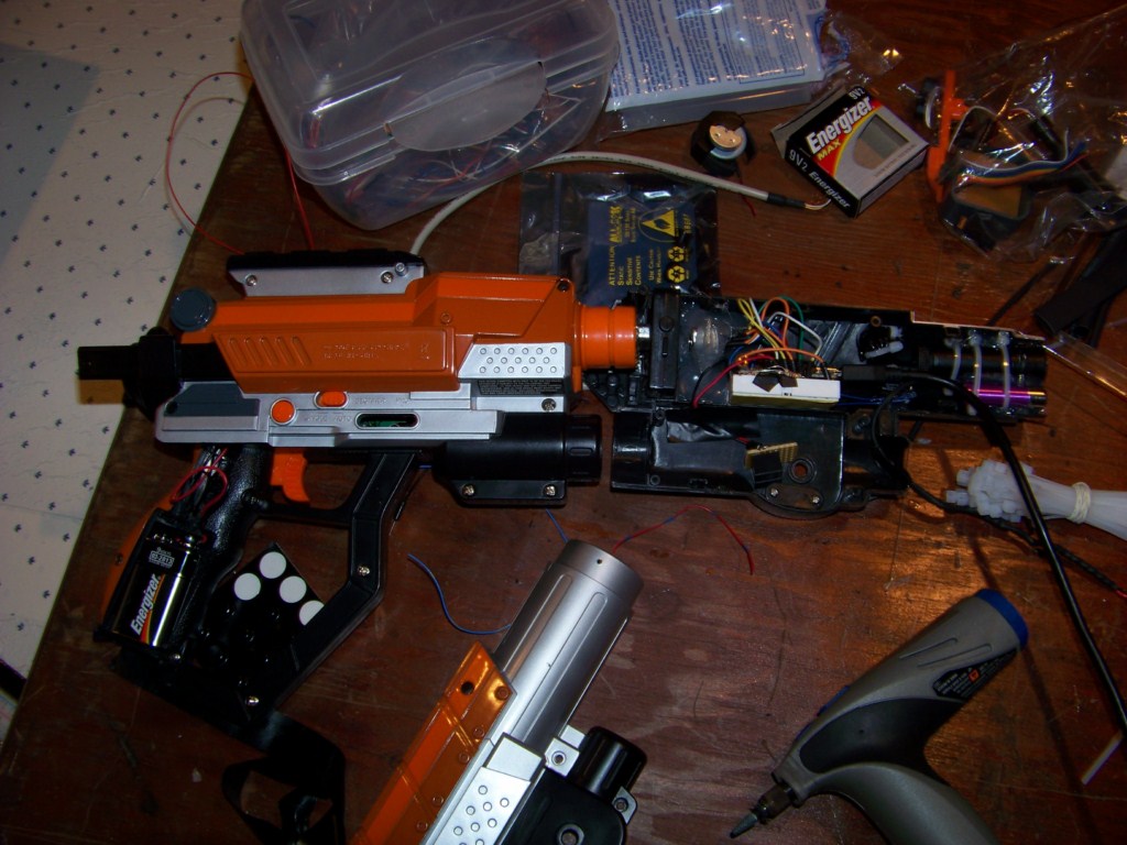
The first picture shows the battery area after I cut off the middle separator. It’s meant for two AA batteries, but once I smoothed everything out, I could easily fit a nine volt in it’s place (which is later changed). The fourth picture shows the connectors I used, minus the motor and the 9 Pin one. I wired the voltage wire dirrectly to the Audio jack, since the “motherboard” of the rifle is on the other half. This way, I can detach both sides if I need to. The final picture shows both halves connected.


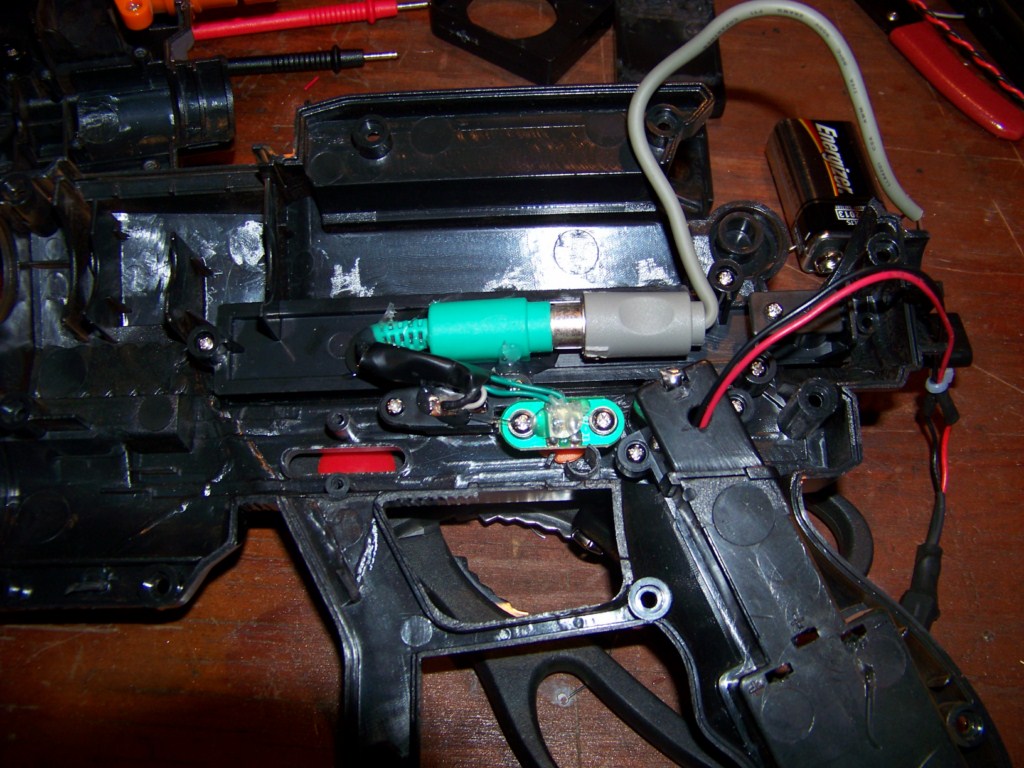

Since the A and Single – Auto button is also on the same side as the 9v battery, I had the same issues. Since I only needed 3 wires, I found a spare PS/2 connector used for keyboards and rigged it up. Yes, it is overkill and huge, but it works for now.
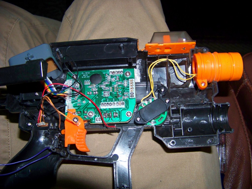


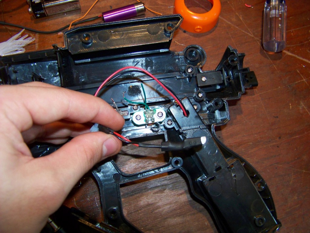
These pictures show the other half. As you can see in the second picture, I cut the motherboard in half to save room, and started to wire things up in the third/fourth. The speaker in the first picture (yellow wires) is removed in the later versions, since I ran out of pins. The wire connecting everything together leads out the barrel.
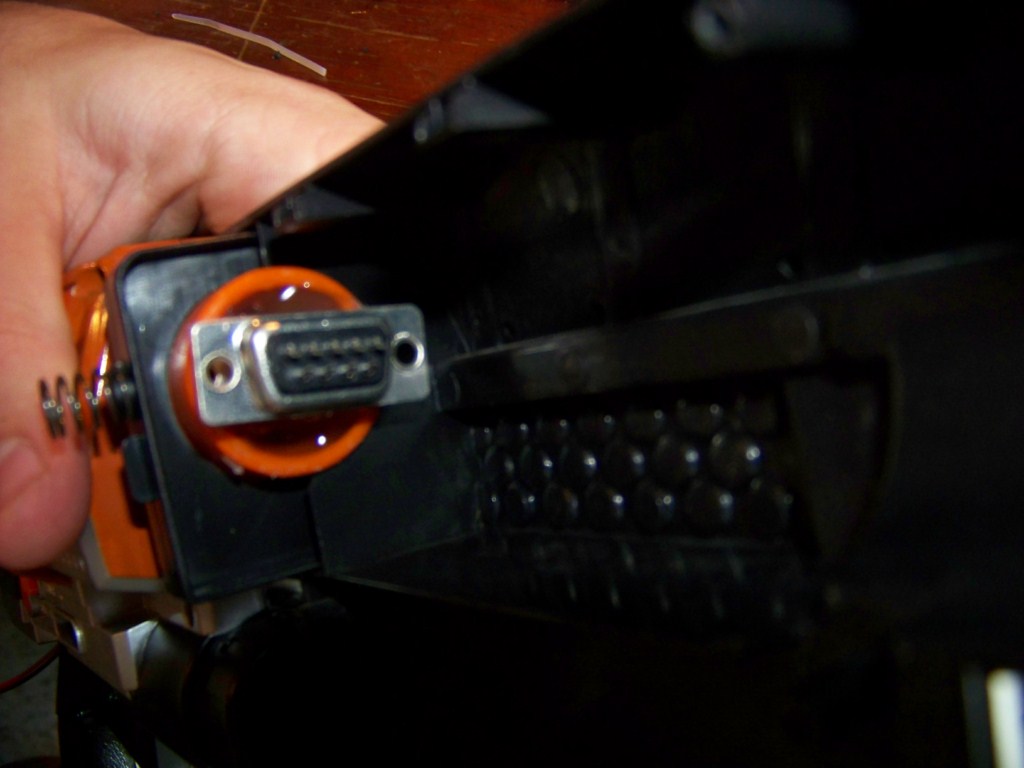


In these pictures, I’m experimenting with the connector. The spring thing you see in picture one and two is a lock, so that once you push the gun into the barrel, they lock together until a release button is pressed. This is perfect for preventing accidental disconnections. In the final picture, it is cut to size, and hot glued in place.


In these pictures, I cut wires with pins at the end, and hot glued them into the other half of the connector. Using a mini-breadboard with a sticky underside, I was able to fit an Arduino Nano 3.0 in the buttstock, and push the pins in the correct spots. I love this method, since once the rifles components are all soldered to the connector, I can seal up the gun and only deal with the barrel. This also saved me when I mixed up a few pin numbers, and had to swap them. It would have been messy if I had soldered them together. As for the breadboard, a couple rows of pins are grounded, for reasons I will get into at the end. Also, the solenoid relay controller, which powers the solenoids that will eventually be used as recoil, is visible under the breadboard, soldered together on the grey/yellowish thing.


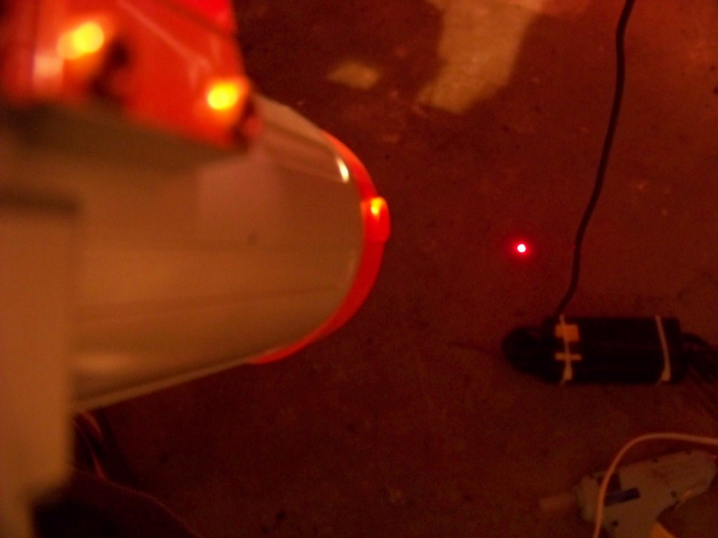

These pictures show the red and IR laser. The red laser was repurposed from the first version of the R1FLE, with a few tweaks. The red laser already had the batteries inside, and when the two wires comming out the end touched, shined the red dot. This caused problems, since I needed a relay to do this, and I originally did do it that way. However, as testing continued, the batteries ran out, bringing up other issues with brightness, and also timing since the relay added a few milliseconds to the time it took to shine the dot after the arduino triggered it. Eventually, I took it apart and wired it the same way I did the IR, with the ground wired to ground, and the voltaged wired to an arduino PWM pin. PWM, or Pulse Width Modulation, changes the voltage the arduino outputs (from normal 5v steady) to any variable between 0-255, by adding small pulses of 0v in between. By adjusting the number, the arduino quickly sends out pulses of eithe 0v or 5v at incredibly fast (yet different rates, depending on the integer chosen) rates, essentially averaging the number. So even though the arduino is pulsing 0 and 5 volts quickly, a multimeter would pick it up at something like 3v, or anywhere between 0-5v, depending on where between 0-255 you chose. The great part about using PWM is that I can quickly test what voltage makes both lasers the best, as nothing is set in stone.


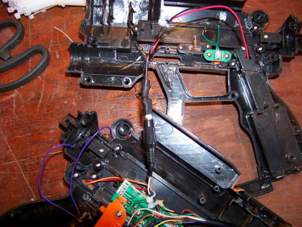
The first picture shows the barrel and rifle connected, while the second shows them apart. Again, the solenoid recoil controller is visible in the lower barrel. The barrel lock works perfectly, keeping the connections snug. The final picture is the R1FLE MK II, minus the battery plate.

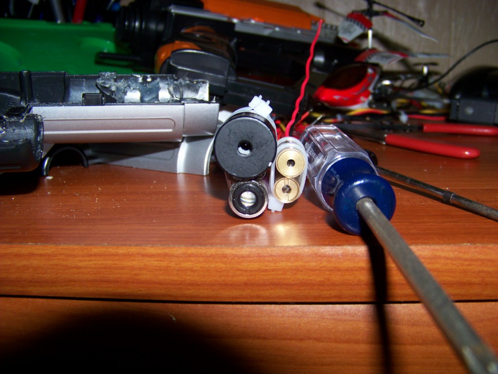
These pictures were taken after the arrival of my new lasers, and are set next to the old ones for size comparison.


The fitting of the lasers in the barrel had a simple solution. In order to keep the lasers centered, I used popicicle sticks to move them twoards the middle. The final picture shows the view from the front.


The first picture shows the new layout, which includes an xBee. The second shows the 5v Battery that now is implemented, removing the laser.
What's Next
I’m thinking about adding a second connector at the bottom barrel area. While right now the connector is at the top yellow barrel, the bottom black one also connects together. This would leave me 9 more pins to work with, which would allow things such as power indicators, the LCD display, and possibly even use of the speaker.
Speaking of the LCD, I have no clue how it works, and the wires are labeled confusingly. Possibly after much more tweaking, I’ll be able to use it, but with the amount of wires, I may need another arduino working in conjunction with the first just to use the thing. For now, a simple 3 wire alternative is being developed, which is basically just two 8-Segment displays, allowing two digits to be shown for remaining ammo.
Also, the grounds on the breadboard are used for the connectors. All input pins are connected to ground through a 10kohm resistor, so that by default they are ground. All the buttons and switches are connected to 5v, so when one is pressed or switched, 5v reaches the pin, and then flows through the resistor and to ground. This is prevents floating pins, which is when no input is connected, so the arduino randomly switches between thinking ground and 5v is connected. With the grounded resistors, it is always either 5v, or when in lack of 5v, it’s ground by default.
The other big step is switching the modes around. Eventually, I plan on implementing a gyroscope (which also calls for another arduino, so most likely I’ll end up with two in the case, there is plenty of room in there), and having A mode powering down all lasers, and instead using the gyroscope. Other smaller tweaks, such as changing recoild time (and actually implementing the solenoid for recoil, although the relay controllers for it are already in there.
I’ll also get a video up ASAP.
Current Arduino Code
/*
R1FLE Arduino Code Version 0.1
Coded by Michael Fessenden, www.mikefez.com
Notes:
All Buttons/Switches pulse HIGH when active, LOW by default.
PWM: 3, 5, 6, 9, 10, and 11
5v/255= 0.0196  [---]   0.0196 X PWM num = Voltage
*/
const int aButton = 2;  // pulses HIGH on push
const int triggerPin = 3;  // receives HIGH when pulled
const int recoilPin = 4;  // pulses HIGH on trigger, normally LOW
const int rButton = 5;  // pulses HIGH on push
const int semiburst = 6;  // set as SEMI when HIGH, BURST when LOW
const int aMode = 7;  // HIGH when set. If A/B are both LOW, C is active
const int bMode = 8;  // HIGH when set. If A/B are both LOW, C is active
const int redLaser = 10;  // Toggle HIGH to show, analogWrite(redLaser, redPWM)
const int irLaser = 11;  // Toggle HIGH to show, analogWrite(irLaser, irPWM)
const int greenLED = 13;  // receives HIGH when Saftey is off

const int irPWM = 200;
const int redPWM = 200;

int selectorswitch = 0;
int triggerState = 0;  // variable for reading the trigger status
int aModeCheck = 0;
int bModeCheck = 0;
int firingmode = 0;
int serialval = 0;

void setup()
{
  pinMode(aButton, INPUT);
  pinMode(triggerPin, INPUT);
  pinMode(rButton, INPUT);
  pinMode(semiburst, INPUT);
  pinMode(aMode, INPUT);
  pinMode(bMode, INPUT);
  pinMode(recoilPin, OUTPUT);
  pinMode(greenLED, OUTPUT);
  pinMode(redLaser, OUTPUT);
  pinMode(irLaser, OUTPUT);
  digitalWrite(recoilPin, LOW);
  analogWrite(redLaser, LOW);
  analogWrite(irLaser, LOW);

  Serial.begin(9600);
  Serial.flush();
}

void loop()
{
  aModeCheck = digitalRead(aMode);
  bModeCheck = digitalRead(bMode);

  if (Serial.available())
  {
    serialval = Serial.read();
    Serial.println(serialval);

    if (serialval == 'R')  //Recoil Test
    {
      digitalWrite(recoilPin, HIGH);
      delay(500);
      digitalWrite(recoilPin, LOW);
    }
    serialval = 0;
  }

  if (aModeCheck == HIGH) {// A MODE, To Be Gyroscope
    firingmode = 1;
    digitalWrite(redLaser, LOW);
    analogWrite(irLaser, irPWM);
  }
  else if (bModeCheck == HIGH) {// B Mode, IR and Red Laser Pulses
    firingmode = 2;
    digitalWrite(irLaser, LOW);
    digitalWrite(redLaser, LOW);
  }
  else if (aModeCheck == LOW && bModeCheck == LOW) {// C MODE, IR and Red Laser Constant
    firingmode = 3;
    analogWrite(redLaser, redPWM);
    digitalWrite(irLaser, LOW);

  }
  triggerState = digitalRead(triggerPin);
  if (triggerState == HIGH){
    digitalWrite(greenLED, HIGH);
    recoil(firingmode);
    delay(300);
    digitalWrite(greenLED, LOW);
  }
}

void recoil(int mode)
{
  selectorswitch = digitalRead(semiburst);
  if (selectorswitch == LOW) {//SEMI
  Serial.print("Mode 1");

    if (mode == 1){
      //Nothing Yet
    }
    if (mode == 2){
      analogWrite(irLaser, irPWM);
      analogWrite(redLaser, redPWM);
      digitalWrite(recoilPin, HIGH);
      delay(25);
      analogWrite(irLaser, LOW);
      analogWrite(redLaser, LOW);
    }
    if (mode == 3){
      analogWrite(irLaser, irPWM);
      digitalWrite(recoilPin, HIGH);
      delay(25);
      digitalWrite(irLaser, LOW);
    }
  }
  else {//Burst
  Serial.print("Mode 2");

    if (mode == 1){
      //Nothing Yet
    }
    if (mode == 2){
      for (int x = 0; x < 3; x++) {
      analogWrite(irLaser, irPWM);
      analogWrite(redLaser, redPWM);
      digitalWrite(recoilPin, HIGH);
      delay(25);
      analogWrite(irLaser, LOW);
      analogWrite(redLaser, LOW);
      delay(100);
      }
    }
    if (mode == 3){
      for (int x = 0; x < 3; x++) { //Fires a three round birst
      analogWrite(irLaser, irPWM);
      digitalWrite(recoilPin, HIGH);
      delay(25);
      digitalWrite(irLaser, LOW);
      delay(100);
      }
    }
  }
  digitalWrite(recoilPin, LOW);
}
Leave a Reply